I designed wind turbine blades for my group’s first iteration wind turbine using MATLAB.
I imported NACA profile xyz coordinates into MATLAB and manipulated the coordinates along the length of the blade
to produce the desired pitch and twist angles and chord lengths.
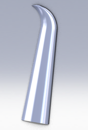
After generating xyz coordinates for a full length blade in MATLAB, I imported the coordinates into SolidWorks in order to create
an .stl file. Finally, I used the .stl file to 3D print the blades using ABS plastic. Part of this page was generated automatically from MATLAB.
Contents
ME 43 Design project 10/01/11
Author – Jonah Kadoko
Tufts University
I wrote this script to create wind turbine blade airfoil profiles. The profiles’ (x,y,z) coordinates are in .sldcv files that can be easily imported into SolidWorks as curves. With these curves, one can use the loft feature to generate a 3D design of the blade. I developed this script to design blades for a cellphone charger turbine.
- To run the script, download a Airfoil generator package from MATLAB website: here
- Download the following package inorder to use the centroid.m function: http://www.mathworks.com/matlabcentral/fileexchange/7844-geom2d/all_files
% Here are the inputs of the script:
%     l  - inches . The incremental length of the turbine blade ( l <=
%                   totallength)
%     totalLength - (inches) total length of the blade ~ 4 inches
%     tipThick   - (inches) the thickness of the blade tip
%     L0  - inches) the length were tapering starts
%     tipCurveL   - inches)  length were the blade-tip starts to curve
%     tipCurveR   -inches ) the radius of curvature of the blade-tip
%     4415 - NACA airfoil code - I decided to use 4415
%     cl - the percentage length where twisting stops
%     theta(l) - twist angle as a function of blade incremental length (I
%                 suggest you modify this function to create a smooth
%                 twist: fitting a 3rd order polynomial might do it)
%     twistAng - (rad) calculated by theta(l)

% Outputs:
%     xyz#.sldcrv  - (x,y,z) points defining a curve. Import these into
%               SolidWorks and use the loft function to create the blade.
%               there are about 20 of these files, you do not have import
%               all of them as long as you import profileLine.sldcrv.
%     profileLine.sldcrv - (x,y,z) points defining a the guideline for the
%               blade. Import it into solidworks. Loft will ask for a
%               guide curve, use this curve to create a smooth blade.

close all;clear all
totalLength=4; % inches total length
baseThick=1; % inches - the thickness of the base
tipThick=0.5; % inches - thickness at the tip
L0=0; % inches - starting length (where you reduce the thickness)
l=0:0.1:totalLength;n=0;
tipCurveL=3.25; % inches - the place where blade tip curves backwards
tipCurveR=totalLength-tipCurveL; % the radius of curvature of the tip

% defining variables for naca4gen.m
iaf.designation='4415';
% designation='0008';
iaf.n=30;
iaf.HalfCosineSpacing=1;
iaf.wantFile=1;
iaf.datFilePath='./'; % Current folder
iaf.is_finiteTE=0;
blade = naca4gen(iaf);

% plot(af.x,af.z,'bo-')
s=5;
l1=length(blade.xU);l2=length(blade.xL(2:end));
xyz=[blade.xU blade.zU;blade.xL(2:end) blade.zL(2:end)];
lxyz=length(xyz);
[IDX, C0]=kmeans(xyz,1); % this calculates the centroid of the airfoil
% Write the coordinates to a text file
% calculate the location of the tip curve center of mass
tipCurveCenter=[C0(1)+tipCurveR, tipCurveL];
theta0=0;    % the starting pitch angle at the root in deg
cl = 0.8 ; % default is 0.8 (80% the length)
theta=@ (l) -(theta0/(cl*totalLength))*l+theta0;
% set the folder to write the turbine profile data.
cd('C:\Users\[type the folder to save the output files]');
% Change this folder to a folder on your desktop. The script will write
for l=0:.2:totalLength
    n=n+1;
    %     create a new filename
    nstr=num2str(n); % changing the n to string
    filename=strcat('xyz',nstr,'.sldcrv');
    %     calculations
    thickC=(baseThick-tipThick)/(L0-totalLength)*l+baseThick;
    tempXYZ=thickC*xyz;
    z(n,1)=l;
    % this is for aligning the centroids of the airfoils
    Ct=centroid(tempXYZ); % Download it from Mathworks website
    if l>=tipCurveL
        %         at this point, the blade will start to curve back along a
        %         circular path of 0.75
        theta=asin((l-tipCurveCenter(2))/tipCurveR);
        xShift=[tipCurveR-tipCurveR*cos(theta) 0];
    else
        xShift=[0 0];
    end
    if l<cl*totalLength % if the l is less than cut-off length
        twistAng=theta(l)*pi/180;
        M=[cos(twistAng) -sin(twistAng); % rotation matrix
            sin(twistAng) cos(twistAng)];
    else
        M=eye(2);
    end
    %         shift center of mass
    tempXYZ=tempXYZ+repmat((C0+xShift-Ct),lxyz,1);
    %         rotate by twistAng
    tempXYZ=M*(tempXYZ');
    %         final value  subrated the shift of the center of mass

    profile(n,:,:)=[tempXYZ' l*ones(lxyz,1)];
    profileLine(n,:)=[profile(n,1,1) profile(n,1,2) l];
    tempM(:,:)=profile(n,:,:); % this is after realization that dl
    %     dlmwrite does not work with 3D matrice
    %      dlmwrite(filename,tempM,'delimiter','\t','newline','pc'); % write a file
    %      import these files into Solidworks as curves
end
dlmwrite('profileLine.sldcrv',profileLine,'delimiter','\t','newline','pc');
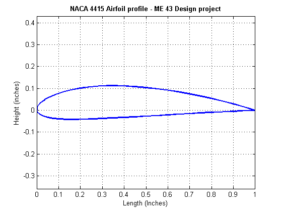
Plotting the airfoil profiles 1
Generate the airfoil shape of the blade at lengths along the blade.
plot(profile(1,:,1),profile(1,:,2),'LineWidth',2 );
hold on
% subplot(1,2,1),plot(profile(40,:,1),profile(40,:,2));
axis equal
title ('NACA 4415 Airfoil profile - ME 43 Design project','FontWeight','Bold')
xlabel ('Length (Inches)')
ylabel 'Height (inches)'
grid on; hold off;
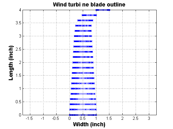
Plotting the airfoil profiles 2
plot the frontal view of the blade
plot(profile(:,:,1),z,'xb') ;
title('Wind turbine blade outline','FontWeight','bold','FontSize',14);
xlabel ('Width (inch)','FontWeight','bold','FontSize',14);
ylabel ('Length (inch)','FontWeight','bold','FontSize',14);
axis equal; grid on;

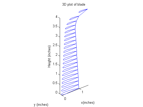
Plotting turbine blade in 3D :
figure;
[n,x,y]=size(profile)
for iter=1:1:n
    %     loop through the data points and plots profiles of airfoils

    plot3(profile(iter,:,1),profile(iter,:,2),profile(iter,:,3));
    hold on;
end
axis equal
plot3(profileLine(:,1),profileLine(:,2),profileLine(:,3));hold off;
xlabel('x(inches)');ylabel('y (inches)');zlabel('Height (inches)')
title('3D plot of blade');
% this is a plot of the frontal area of the blade
n =

    21


x =

    61


y =

     3
3D image of the blades in SolidWorks: