Heat Pumps for Concord, MA
[Image from ecotope.com]
In this project I did the following:
- Wrote detailed technical background about heat pumps.
- Formulated an algorithm to approximate building thermal resistance of a given house given 2+ years worth of heating bills.
- Programmed the above algorithm in VBA for Excel.
- Presented project findings to the town of Concord and CSEC.
Below is a technical summary of heat pump technology that I put together. You can also read about the project at Tufts School of Engineering web page.
1. Technical Overview of Air-Source Heat Pumps
Just as the name suggests, air-source heat pumps move heat from the atmosphere to a living area, or vice-versa depending on the operation mode (heating or cooling). The air-source heat pump consists of two units as shown in Figure 1: an outdoor and an indoor unit. The outdoor unit (number 1) moves heat from the atmosphere to the refrigerant by vaporizing the refrigerant. The vaporized refrigerant is then condensed within the indoor unit (number 4), thereby releasing the latent heat of vaporization to heat the indoor living space. During the warmer season, the flow of the refrigerant is reversed using a built-in reversing valve such that the indoor unit extracts heat from the living space whilst the outdoor unit releases heat to the atmosphere.
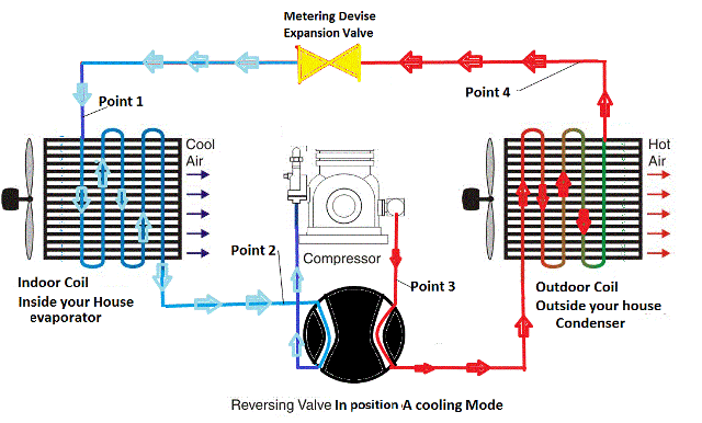
Figure 1 Schematic of a typical heat pump in the cooling (left) and heating (right) mode (from http://www.heatpump-reviews.com/heat-pump.html#gallery [pageGallery]/3/).
There are three main design categories of air-source heat pumps, specifically ducted heat pumps, ductless mini-split heat pumps and air-to-water heat pumps. Each has advantages in certain situations. Ducted heat pumps are most appropriate for houses with pre-existing ductwork and central air-systems, whereas ductless mini-split heat pumps are more suitable for houses without pre-existing heat distribution systems. Air to water heat pumps are ideal for houses that already have hydronic heating systems. To keep costs low, a heat pump should fit into the pre-existing heating system.
2. Selection Criteria for Heat Pumps
There are many factors for a homeowner to consider when choosing a heat pump. A high efficiency, low temperature rated heat pump is necessary for meeting heating needs for winter weather in New England. Other system features for a homeowner to consider include heat source (air or ground,) seasonal energy efficiency ratio (SEER), heating season performance factor (HSPF), heat pump size, source of power for the compressor, method of heat distribution, number of compressors and compressor speed.
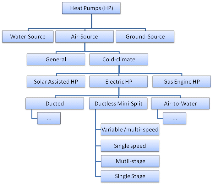
Figure 2 General overview of heat pump technology
2.1. Heat Source: Air vs. Ground
There are two major sources of heat for heat pumps, air and ground, each with its own advantages. Air-source heat pumps tend to have lower installation cost while ground source heat pumps have higher installation costs. Ground source heat pumps on the other hand, are ideal and predictable because ground temperatures do not vary so much from season to season.
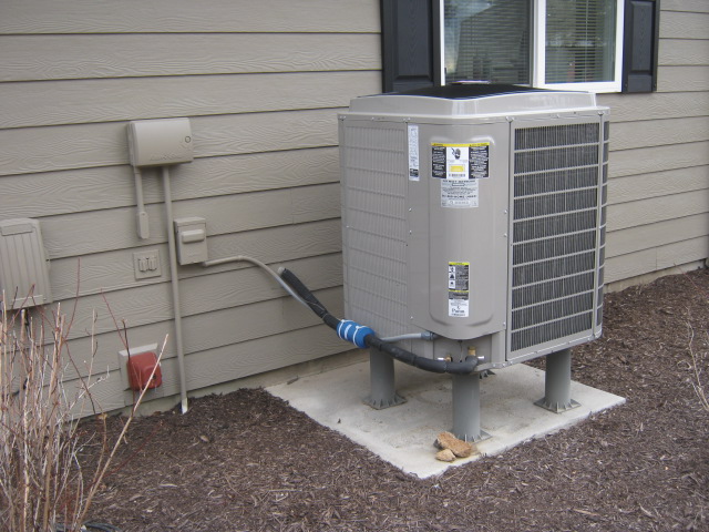
Air-source heat pumps are the most common heat pumps. They consist of a split outdoor unit and indoor unit, hence the name split air-source heat pump. The outdoor unit is mounted in an outdoor open space and connected to the indoor unit via tubes of refrigerant. The availability of heat and performance of ASHPs depends on the outdoor ambient temperatures. At lower outdoor temperatures, ASHPs consume more electrical energy to extract the same amount of heat from the outside.
There are two main types of ground source heat pumps (GSHPs). One consists of ground loops buried in 3-to-6.5 ft deep horizontal trenches around the served building. The other type of system uses pipes laid in 320-to-500ft bore-holes [1]. Excavation and drilling constitute a major portion of the cost and technical challenge of ground source heat pumps. A homeowner can reduce cost of ground source system by installing the ground loops at the time of construction when excavators are already on site or by partnering with neighbors to sink a communal bore-hole from which several heat pump systems can be connected to.
Both air and ground source systems may suffer efficiency losses if poorly designed. If ground loops are closer together, the system may extract excessive heat from the ground such that the ground does not recover to normal temperatures leading to poor performance of the GSHP over time [1]. For air-source heat pumps, one has to be careful about the brand and model of the heat pump system as some models are not designed to operate in cold outdoor temperatures typical of New England.
2.2. Heating Seasonal Performance Factor (HSPF)
HSPF (measured in BTU/kWhr) is a North American standard metric of how well a heat pump meets a building’s heating load per given kilo-watt-hour of electricity supplied to the heat pump. An HSPF above 10 is recommended for Concord residents [2] [3]. The HSPF is a standard metric, meaning all heat pumps in the US are tested and measured using one set of climatic conditions, which is AHRI climatic region 4 [4]. However, AHRI climactic region 4 is one of many climate regions in the US, and building loads change from one climatic region to another, so often the installed HSPF of a heat pump may not match the listed HSPF. To a resident in Concord, it can be safe to assume that the installed HSPF of the heat pump will be close to the listed HSPF because Massachusetts is divided between climatic region 4 and 5 [4].
HSPF is calculated by dividing the total seasonal building load (BL) with the sum of total seasonal electric energy consumed by heat pump (eh) and resistive heater (RH) all multiplied by a defrost factor (Fdef). Building load is the amount of heat that must be supplied to a building to maintain a comfortable internal temperature. Building load depends on the integrity of the building insulation, air filtration, climatic region, solar heat gain and occupants’ comfort temperature. A heat pump consumes electricity to operate fans, electronics, compressors, and any other electrical parts so large electricity consumption tends to lower the HSPF value. All these parameters are shown in the equation below,
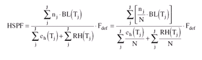
Where N is the total number of heating hours of a given climatic region established by AHRI Standard 210/240 as shown in Appendix, nj is the total number of hours that temperature falls within the temperature bin Tj, and J is the total number of temperature bins.
The calculations for HSPF are very similar to those for the COP. To differentiate the COP from HSPF, HSPF (in BTU/kWhr) is divided by 3.41213 BTU/kWhr.
2.3. Seasonal Energy Efficiency Ratio (SEER)
SEER is the standard metric used to measure how well a heat pump can cool a living space per unit of electric energy supplied to the heat pump. SEER above 20 is generally recommended [3]. To a homeowner in a cold climatic region such as Concord, SEER is of little importance when compared to other factors. Heat pumps sized for heating loads in cold climate regions are already oversized for the cooling load. Cycling losses will result because the load is small compared to the capacity of the heat pump so installed SEER will be lower than listed SEER. One solution to avoid cycling losses is to choose a heat pump that has a compressor with variable speed as discussed latter in the report.
SEER is calculated by dividing the total seasonal cooling load by the total electric energy consumption. Similar to HSPF, SEER is measured in units of BTU/kWhr and can be changed to COP by dividing by 3.41213 BTU/kWhr.
2.4. Heat Pump Sizing
An ideal heat pump should be large enough to meet the heating and cooling load of the living space. Large heating loads call for large capacity heat pumps. One caveat is that cost increases with increasing heat pump size so it may be wise for a homeowner choose a small heat pump that operates side-by-side with an oil or gas furnace or a resistive heater. Either way, it is imperative to have detailed knowledge of the total heating load.
The heating load is the amount of heat energy required to maintain a comfortable indoor temperature. Heat is required to make up for the heat lost to the environment, so in an idealized case of a well-insulated house, there is no need for a heat pump because there is no heat loss. However, in practical houses, heat is constantly lost through poor insulation, roofs, windows, open doors, air infiltration and through basements. In addition to heat loss, a house gains heat energy from computers, TVs, stoves, driers, human occupants and solar energy [5]. It is good practice to sum up all heat losses and gains accurately in order to size the heating system.
It should be noted that, due to the specificity of the heat loss and heat gain mechanisms, every house in Concord is bound to have a different heating and cooling load. Therefore, the final sizing of a heat pump should be done by a licensed HVAC professional; a homeowner may perform initial estimates for preliminary planning using the heat pump performance calculator, but this should not be used for final designs. A homeowner may use initial estimates of heating and cooling loads to plan accordingly and reduce system size by eliminating air leakages, improve insulation, double or triple glazing windows, harnessing passive solar thermal for space heating, and good habits such as keeping doors closed[5]. If the homeowner is applying for MassCEC incentives, all official calculations of heating loads are required to be performed using ACCA Manual J heat load calculations [6].
2.5. Cold Climate Air-Source Heat Pumps (CC-ASHP)
Cold climate air-source heat pumps are optimized to solve heating and cooling challenges in areas that experience low temperatures around 0 ̊ F [5]. Cold climate areas, such as Concord, typically have higher heating than cooling loads and may experience temperatures below operating temperatures of most air-source heat pumps. To a homeowner, an ideal heat pump should be able to meet the entire heating load during the winter, but that may not be technically possible for a variety of reasons. The coefficient of performance (COP) of a heat pump decreases at low ambient temperatures. Furthermore, a heat pump sized to meet the heating load in Concord is oversized for the summer [5].
To address the challenges of cold climates, design improvements are required to make a regular ASHP good enough for cold-climates. Such design improvements include the following:
- Sizing heat pump for the heating load ensures that the heat pump has sufficient heating capacity at low temperatures. If sized to meet the lowest annual temperatures, this may lead to a large system and higher installation cost, it may be wise to size the unit to a moderate temperature and supplement heating capacity with resistive heating in the coldest days. An oversized system may result in cycling losses (discussed latter in the paper).
- Geothermal heat pumps are ideal for cold-climates because ground temperatures are fairly constant throughout the heating season. However, geothermal heat pumps come at exorbitant installation costs.
- Oversized outdoor coil makes it possible for the heat pump to extract more heat from the outside air [5].
- Use of carbon dioxide as a refrigerant can increase the capacity of a system by about 35% at temperatures of 17 ̊ F [5].
Currently, there are research efforts through the Department of Energy (DoE) to design high performance cold climate heat pumps that can achieve a COP upwards of 3 at -17 ̊ F (-25 ̊ C) [6]. Although none of the proposed designs are yet in the market at the time of writing this report, 17 heat pump models from Mitsubishi and Haier are classified, by Northeast Energy Efficiency Partnership (NEEP), as CC-ASHP by virtue of the following characteristics:
- COP greater than 1.75 at 5 ̊ F,
- Energy Star certification,
- variable capacity compressor,
- matching indoor and outdoor units and
- HSPF ³ 10 for single-zone system and HSPF ³ 9 for multi-zone system [3].
After all, the choice for CC-HSPF model is dictated by whichever body administers the best incentives or has local jurisdiction. Currently MassCEC has incentives for a select list of Daikin, Fujistu and Mitsubishi ASHP models [7]. It is recommended that the town of Concord adopts the MassCEC and or NEEP criteria to approve heat pump models for residential use.
2.6. Heat Pump Power Source
As previously stated, the majority of the electrical energy used in the operation of a heat pump is utilized in powering the compressor. The compressor converts this energy into mechanical energy. This means that the electric motor in the compressor could, potentially, be replaced by a combustion engine. Gas or oil can be used to power the engine to form what is known as gas engine heat pump (GEHP). Currently there are not many models of engine powered heat pumps in the American market. This type of system may make sense for a homeowner who is off-grid, in areas where gas prices are cheaper than electricity or in cold climates. In either scenario, from an efficiency and emissions stand-point, burning fossil fuel on-site may be more efficient than burning fossil fuel to generate electricity at a distant electric power plant where there are generation and transmission losses [1]. An advantage of all gas engine heat pumps is that additional heat can be extracted from the heat engine body and the engine can function as a supplemental heat source at cold temperatures [1].
Another form of heat pump, called absorption heat pumps, burn fossil fuels to separate ammonia gas from an ammonia-water solution in a generator-absorber heat exchanger (GAX) [8]. In this type of a system, ammonia is used as the refrigerant to replace ozone-depleting refrigerants. Most absorption heat pumps that have been developed so far are powered by natural gas, so they are sometimes called gas-fired heat pumps. Absorption heat pumps are still under development, systems that are on the market have efficiencies of less than 1 whilst systems under research and development have efficiencies between 1.2 and 1.6. The Town of Concord may consider such systems when they become technologically mature in the next few years [8].
A third possible source of energy for heat pumps is solar thermal. Solar thermal collectors can be coupled with heat pump technology in solar-assisted heat pumps (SAHPs).The resultant heating capacity is much higher than conventional ASHPs, but the technical challenges of sizing and matching components present challenges in implementing SAHP technology [1].
2.7. Compressor Motor-Drive
Many heat pumps on the market today contain a single speed compressor. Although it is much simpler and less expensive to have a single speed compressor, the only method to control indoor temperature is to turn the compressor ON and OFF. Because this system only has two modes and no variable speed levels, this system is likely to over or undershoot the desired temperature. Switching between these modes will lead to frequent ‘start-ups’ and ‘shut-downs’, which will cause energy losses (called cycling losses) and discomfort due to large temperature swings [1].
The solution is a multi-speed or variable speed compressor. The difference between multi-speed and variable speed is that in multi-speed there are a set number of discrete permissible speeds whilst in variable speed, an inverter is used to control speed in a continuous range [1]. Inside temperature is controlled by moderating the speed of the compressor leading to smaller cycling losses and smooth temperature control. In addition to improved comfort, the homeowner saves up to 15% by using a heat pump with multi-speed [1]. The efficiency gains are up to 40% in heat pumps that use variable speed control compressors [9].
2.8. Heat Distribution System
Heat from a heat pump can be distributed to multiple rooms in a residential house using ducts and vents; wall mounted refrigerant lines, or hot water radiators. It is recommended that the homeowner choose heat pump units that can integrate seamlessly with the distribution system already in place. Generally, manufactures have several versions of heat pump units to work with all three distribution systems.
3. Heat Pump Performance Calculator
3.1. Assumptions made in the Heat Pump Performance Calculator
The simplicity of the of the program was achieved by making assumptions of homeowners’ habits, potential heat sources, overall building resistance and heat pump efficiencies. Detailed descriptions of the assumptions can be found in the following sub-sections.
3.1.1. Full-Tank after Each Purchase
These calculations assume that a homeowner fills up their tank each time they make an oil/gas purchase. It is therefore safe to assume that the energy content in the purchased oil/gas is equal to the heat energy used for heating the indoor space. This assumption is generally true based on conversations with members of CCSEC.
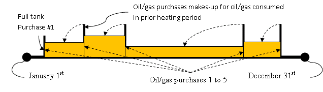
Figure 3 Image showing how the full-tank assumption can be used to calculate the amount of heat used.
3.1.1. Furnace efficiency
This assumption fails for homeowners who use their fuel for other purposes other than space-heating or for homeowners who do not fill-up their tank to maximum at each purchase.
3.1.2. Constant Indoor Temperature
Indoor temperatures are recommended to be constant for optimal operation of heat pumps. If a homeowner has temperature setbacks at night, setbacks should be kept to within a few degrees of peak temperatures. However, the case is different for oil/gas heating systems; homeowners’ programmable thermostats often have significant setbacks at night, during the day or on weekends to minimize oil/gas consumption. [10]
Our calculator does not take into account set-backs or heating profiles in the calculation of heating degree days per heating period for reasons of simplicity.
3.1.3. HVAC System Efficiency
We assume that a general furnace has an efficiency of 75% as typical for older HVAC systems. In simple terms, only a fraction of oil/gas consumption goes into heating the house; some heat is lost in duct systems and furnaces, etc. [11]
3.1.4. Single Heat Source
We assume that the HVAC system is the sole heat source in a residence. In practice, a building can have multiple sources of heat that may include, but not limited to, the following:
- Solar thermal through windows – this is true for un-shaded south-facing windows on a sunny day
- Household appliances – cookers, TVs, stereos, and any other appliance generate heat while in operation.
- Occupants – occupants in the building generate heat.
If heat generation from all sources is summed up, it contributes in reducing the heat consumption at certain times of the day.
3.1.5. Linear Temperature-Dependence of Heat Pump COP
We assumed that COP of heat pumps linearly varies with the outdoor temperature. There is limited performance data on variation of heat pump COP. Heat pumps used in the calculator have maximum and minimum COP at 3 temperature points so linear regression was performed to interpolate COP at other outdoor temperatures as shown in Figure 4.
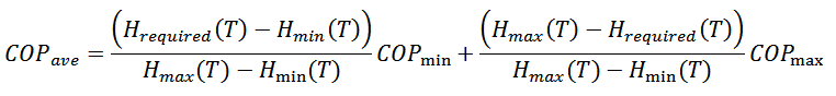
3.1.6. Weighted Average COP
The NEEP heat pump list provides COP at maximum and minimum heat capacities of a given heat pump, but in practice, a residential building has a heating requirement that is between the maximum and minimum heat capacity of a heat pump and sometimes outside this range. We assumed the operational COP is a weighted average of the max COP and min COP with the deviation from required heat as the weight as shown in the following figure and equation.
COP at required heat
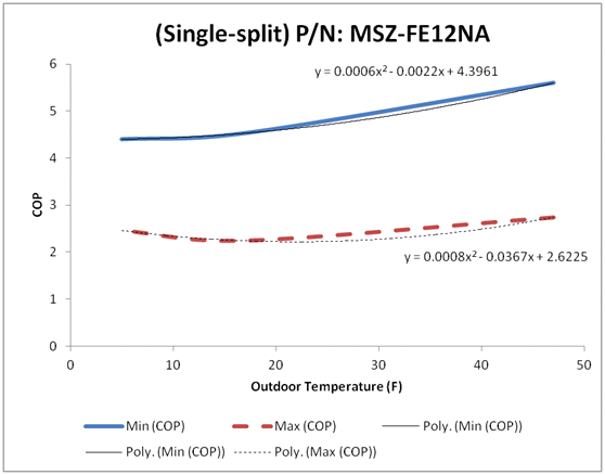
Figure 4 Plot showing variation of COP with temperature and how the operational COP lies between max and min COP. Max COP is the COP at maximum heat pump capacity; it is not necessarily larger than min COP as evidenced in the above plot.
3.2. Description of the Heat Pump Performance Calculator
This heat pump performance calculator was developed to help a homeowner make informed decisions about transitioning to heat pumps using minimal amount of user information. Detailed heat pump sizing calculators such as Manual J require extensive amount of technical information that an ordinary homeowner may not be able to provide instantly. In the calculator, the user has to input one year of oil/gas purchase dates, quantity and cost, indoor temperatures, turn OFF date and turn ON date. A homeowner can easily find this information by reviewing oil/gas purchase invoices and occupants’ habits.
The calculator was programmed using Visual Basic of Applications (VBA) in Microsoft Excel. At the writing of the concept, the calculator is a proof of concept that a knowledgeable homeowner can further customize to meet their individual needs. The following is a flow chart of how this program operates.
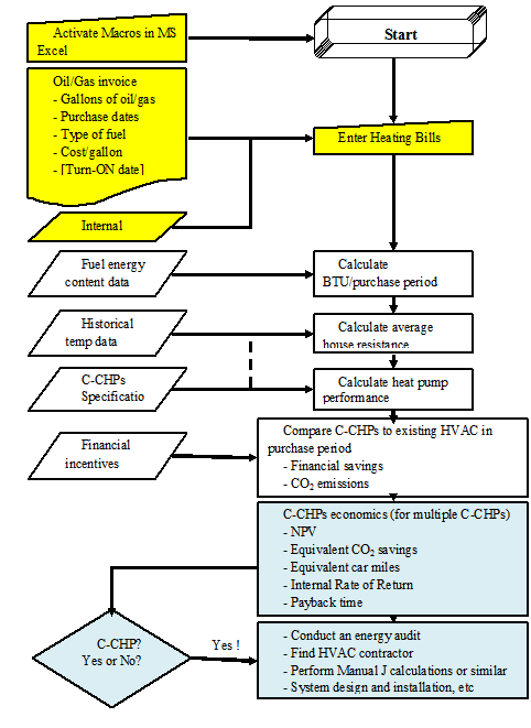
Figure 5 Overview of the calculator
[The rest of the paper continues…the above was my contribution]
Bibliography
| [1] | I. Staffell, D. Brett, N. Brandonc and A. Hawkesd, “A review of domestic heat pumps,” Energy and Environmental Science, 2012. |
| [2] | Efficiency Vermont, “Cold-Climate Heat Pumps,” 13 March 2015. [Online]. Available: Link. [Accessed 17 March 2015]. |
| [3] | NEEP, “Cold-Climate Air-Source Heat Pump Specification,” January 2015. [Online]. Available: Link. [Accessed 17 March 2015]. |
| [4] | AHRI, “Performance Rating of Unitary Air-Conditioning & Air-Source Heat Pump Equipment,” 2008. |
| [5] | K. Roth and J. Brodrick, “Heat Pumps for Cold Climates,” ASHRAE Journal, pp. 69-72, 2009. |
| [6] | U. DoE, “Heating, Ventilation, and Air Condition Projects,” March 2014. [Online]. Available: Link. [Accessed 17 March 2014]. |
| [7] | MassCEC, “Residential Air-Source Heat Pump Program Program Manual,” MassCEC, 25 November 2014. [Online]. Available: Link. [Accessed 17 March 2015]. |
| [8] | R. DeVault, P. Garland, J. Berry and R. Fiskum, “Absorption Heat Pump and Chiller Program,” US DoE. |
| [9] | Y. Cengel and M. Boles, Thermodynamics an Engineering Approach. |
| [10] | Enercom, “Saving Energy with a Heat Pump,” Enercom, [Online]. Available: https://secure.psncenergy.com/enercom/library/savenerg.asp . [Accessed 22 April 2015]. |
| [11] | US DoE, “Furnaces and Boilers,” [Online]. Available: http://energy.gov/energysaver/articles/furnaces-and-boilers. [Accessed 22 April 2015]. |
| [12] | NC Clean Energy Technology Center, “Residential Air-Source Heat Pump Program,” [Online]. Available: http://programs.dsireusa.org/system/program/detail/5635. [Accessed 22 April 2015]. |
| [13] | Mass Save, “COOL SMART Central AC/Ducted Air Source Heat Pump Rebate Program,” 2015. |
| [14] | Mass Save, “COOL SMART Ductless Mini-Split Heat Pump Rebate Program,” [Online]. Available: Link. [Accessed 22 April 2015]. |
| [15] | E. Ambrose, Heat Pumps and Electric Heating, New York: John Wiley & Sons, Inc, 1966, p. 51. |
| [16] | ACCA, “ACCA Speed-Sheets,” March 2015. [Online]. Available: Link. [Accessed 17 March 2015]. |