
History of electric wire insulation
The earliest documented use of plastic electrical wire insulators was in 1812 when India rubber was successfully used as an insulator in the mining industry [1]. In subsequent years, plastic and paper insulation materials were used as insulated wire found uses in telegraphy, power transmission, and lighting [1]. The early insulation material characteristics were found to lack good dielectric properties as demanded by their applications so wire designers proposed new and innovative insulation solutions to obtain superior properties. Cotton infused with shellac or rosin, paper infused with other compounds, jute, oil-filled insulators and natural and synthetic rubber were some of the early innovations [1].
It took several insulation failures between 1880 and 1900s in underground transmission lines for designers to perfect wire insulation technology to what it is today. An important development in underground wire insulation was the successful use of paper saturated with rosin oil in UK in 1890 to transmit electrical power at 10kV [2]. In subsequent years, paper was widely used particularly because its high dielectric strength, low dissipation factor and low dielectric loss meant small thickness of insulation material can be used at a given high voltage [2].
Around the World War II time, the use of natural and synthetic rubber as insulation material grew more than that of paper because of the superior manufacturability and moisture resistance of rubber [3]. Rubber would not have been successful as wire insulation material were it not for the discovery of vulcanization by Goodyear in 1839. In addition to natural and synthetic rubber, new insulation materials included Ethylene-propylene polymers (EPR), high molecular weight polyethylene (HMWPE), cross-linked polyethylene (XLPE) and polyvinyl chloride (PVC) [1]. Although the use of polymeric insulation materials solved many problems in the wire industry, new insulation material failure mechanisms such as water and electrical treeing were discovered in the polymeric materials [3] [1]. As a result, research and development focused on improving electrical and mechanical properties of these polymeric materials either by adding additives, changing manufacturing processes, copolymerization, shielding and jacketing [1].
The history of wire insulation material cannot be complete without mention of the development of standard wire construction styles. In 1894, a young electrical engineer founded Underwriters Electrical Bureau, now known as Underwriters Laboratory (UL), with the purpose of safety testing of electrical appliances and insulation materials [4]. Today, UL tests, certifies and maintains a large database of electrical insulation materials, a large portion of which are plastics. It should be noted that currently there are multiple consensus organization around the world that test and certify wires like UL.
Description of electrical wire insulation plastic
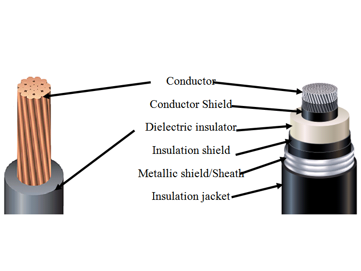
Characteristics of wire insulation plastics are application dependent. In a typical low voltage application, a wire consists of a conductor material such as copper or aluminum and a non-metallic insulating material as shown in Figure 1. In a high voltage application, the insulation of a wire consists of additional layers of a conductor shield, insulation shield, metallic shield and insulation jacket as shown on the right image in Figure 1.
Far from being ideal insulators, plastic wire insulators do permit small, but yet ‘acceptable’ amount of current to flow through them when their rated voltage is applied [1]. This leakage current becomes a concern in high-voltage applications where insulation and metallic shields are added to the conductor to protect insulation material from electrically-induced degradation as shown in Figure 1 [1]. A shield is a conducting layer, either a semiconductor or metal film, that prevents signal interference and insulation damage due to electrical discharges or physical harm [6]. An insulation jacket is an outer covering that provides mechanical protection to a wire.
Concentric to the insulation and at the center, is the electrical conductor. The conductor is typical composed of small strands of wire that are bundled together. The arrangement and size of strands affect the stiffness, current carrying capacity and diameter of a wire, but much of the properties of a finished insulated wire depend on the properties of the insulation plastic plus additives as discussed in latter sections. Each electrical wire application calls for a different set of insulation properties which in turn can be achieved by varying material composition or by changing manufacturing techniques. However, care should be taken when optimizing one property, as some additives and techniques may start to degrade another electrical or mechanical property or may increase cost unnecessarily. Additives include but not limited to fillers, plasticizers, extrusion aids, vulcanizing agents, accelerators, activators, antioxidants and antiozonants [7].
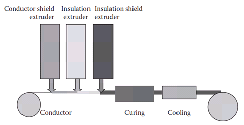
Additives are mixed with the base plastic material in the early stages of the manufacturing process. When the base plastic material and additives are well-mixed, the resulting formulation is then extruded onto a preheated conductor using a plastic extruder. A hook-up wire with a single insulation layer such as the one shown in Figure 1 can be manufactured in a ‘single extruder’ line process in which polymer formulation is extruded onto a pre-heated conductor [1]. For shielded wire, multiple or single pass may be required as shown in Figure 2 [1]. Unlike using distance separated extruders as shown in Figure 2, some extruding heads extrude conductor shield, insulation, and insulation shield at the same time in what is called true triple extrusion [1] [5]. The final processes are curing and cooling.
Bibliography
| [1] | W. Thue, Electrical Power Cable Engineering, New York: CRC Press, 1999. |
| [2] | BICC Cables, Electric Cables Handbook, Oxford: Blackwell Science, 1997, pp. 93-95. |
| [3] | K. Barber and G. Alexander, “Insulation of Electrical Cables Over the Past 50 Years,” IEEE Electrical Insulation Magazine, vol. 29, no. May/June, pp. 27-32, 2013. |
| [4] | Underwriters Laboratory, “UL,” UL.com, 2015. |
| [5] | Southwire, “Southwire Product Catalog,” Southwire, 2015. [Online]. Available: http://www.southwire.com/products/ProductCatalog.htm. [Accessed 10 February 2015]. |
| [6] | U.S. Army Material Command, Engineering Design Handbook: Electrical wire and cable, Washington D.C., 1969. |
| [7] | The Wire Association International, Electrical Wire Handbook, Guilford: The Wire Association International, Inc, 1983, pp. 152, 33, 38. |
| [8] | Anixter, Technical Information Handbook: Wire and Cable, Anixter, 2013. |
| [9] | A. Strong, Plastics: Materials and Processing, Upper Saddle River: Prentice Hall, 2006. |
| [10] | T. Hammons, “Power Cables in the Twenty-First Century,” Electric Power Components and Systems , vol. 31, pp. 967-993, 210. |